Creating a Table
The Clients and Their Home
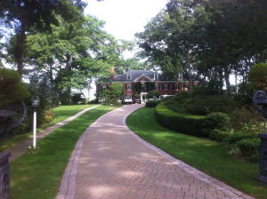
This client and her husband, a CEO of a large tool manufacturer, had purchased a beautiful property in Farmington, Connecticut several years earlier and were completing the decorating process. Apparently the home was built in the 20’s by a successful playwright who wrote for Broadway. The gently curving driveway slowly guides you up to the stately redbrick house on the top of the property which is surrounded by majestic white oaks on all sides. They stand as sentries, shielding the house with their lofty canopies. It’s a beautiful piece of land which requires a handful of people to care for it.
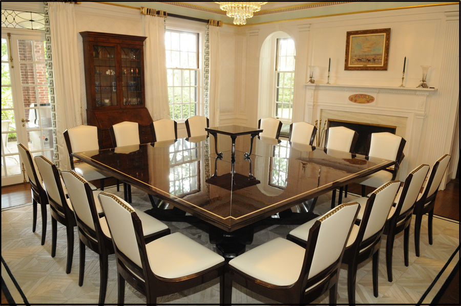
It’s through the front door that the foyer opens up to a grand open space with the stairs on your right and the living room and sun porch on your left. Some of the wood furnishings are prime examples of the art nouveau period while others are simply comfy sofas which invite you to sit down and stay a while. The dining room was at the rear of this large entrance adjacent to the open porch on the backside of the home.
Developing the Idea
I was asked by my colleague Penny Baird http://PennyDrueBaird.com in the fall of 2012 to come up with a dining table design for her client. Few details were offered, other than the dining room was square and that the table had to seat 16. Not a small table I thought, but I had Art Deco on my mind, and so began thinking about the possibilities.
With pen in hand, I sketched out some options and three or four came to mind. All possessed basically the same tops, but the bases varied. Some being more angular and geometric (masculine) and others were more curvaceous (feminine). Being that our client was a woman, the designer and I thought it best to present the more feminine layouts. And so we did.
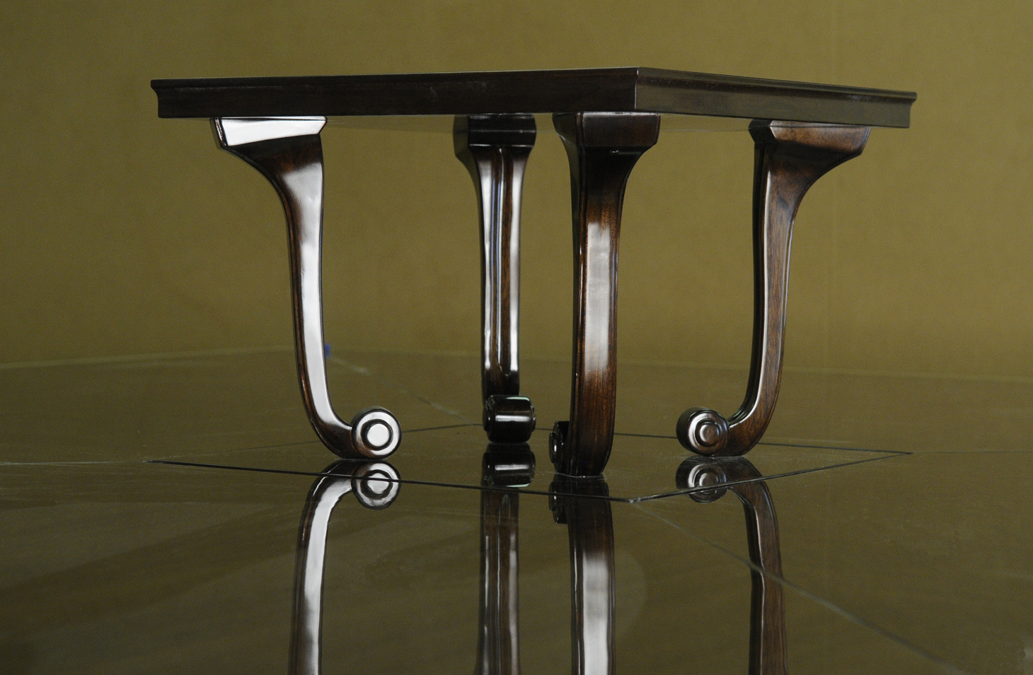
It took a little bit of doing, but the homeowner accepted my design which featured a scroll like or serpentine style leg. Each of which sat on a criss cross base that “floated” above the floor. Only the ends of the base actually made contact with the ground, which kept the entire piece from looking too heavy or monolithic. A piece needs to “breathe” so air must pass beneath it to keep it light on its feet.
Phase Two – The Mock-up
I hadn’t seen the space in person until I was well into the design phase of the project – several months after the initial meeting, but apparently, what I envisioned was well suited for the space.


In a situation like this, where a lot is at stake, I find it necessary to make life size mock-ups out of corrugated cardboard. In doing so, I can demonstrate to the designer, and the homeowner, how their piece will fit into the space, and corrections are easily made.
In this case, a full size top was provided along with the criss cross base and the serpentine legs. Every major feature was accurately represented in cardboard. We wouldn’t want any surprises, now would we?
The Challenge
It was during this phase, however, that the client made a significant request. She wanted a platform within the center of the table that would go up and down depending on whether or not she wanted to display a floral arrangement. This was a game changer for two reasons because it forced me to come up with a manual lift mechanism, but also forced me to re-think how the entire table was going to be engineered. After all, the table top probably weighs 400 pounds.
The original idea was to connect the opposite legs together with cross bars, but now there was a new element in the center of the table which wouldn’t allow for this approach. So I enlisted the services of a welder and built a steel cage around this lift mechanism, thus acting as the backbone of the table. From the upper corners of this cage, four heavy duty threaded rods were attached and connected to the tops of each leg. The cage was also bolted to the heavy criss cross base to create an immovable and rigid support structure. In the end, it worked beautifully.
The other realization I had while in the client’s home, was that an eight by eight foot top would never fit through the front door. So I had to adjust my thinking and make four trapezoidal top pieces that met in the middle and surrounded the center platform. It worked great!
Phase Three – Selecting the Wood
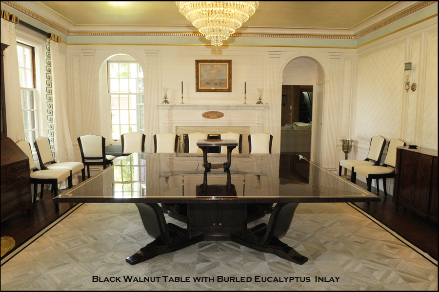
This task was actually pretty simple. All along, the designer and I were looking at black walnut, but which cut of wood remained to be seen. Being that the veneer on the top radiated out from the center, we needed something that would be fairly linear. So I selected a quartered and figured black walnut flitch and made a finished sample.
The headache came when we tried to figure out what the boarder material would be. I tired birdseye maple and then Carpathian elm, creating samples as I went. Neither succeeded so I moved onto my favorite,… burled eucalyptus. This was my choice because contrasted nicely with the walnut. With a little cajoling, some revisions, and a few more samples, the client was coaxed into this combination.
Veneering Decisions
Now that all the crucial decisions had been made, it was time to build. I sent my drawings to my veneer man and we discussed how the veneer would be applied to each piece of the table. The top was his responsibility, the base was mine.
Each table top section required 24 leaves of veneer, which meant four bundles of material. All of which came from the same tree and were sequential. In order to maintain a consistent pattern, we used the same section of each veneer leaf from each bundle and slip matched them. As I said, the pattern radiated out from the center, so we knew, that the veneer leaves from the first table top section would eventually meet the leaves from the adjacent piece, so it was important that they lined up. The pattern of each section mirrored the ones next to it. In other words, they were book matched and all the seams lined up perfectly. Even the veneer for the center display platform was spot on.
With the remaining veneer, I requested that the leaves be joined and laminated onto a backer panel such that I would have, say 24 x 36 inch flexible panel for the serpentine table legs. And that some material would be applied to center cabinet for hiding the lift mechanism.
Construction
The Top
The veneer man in Brooklyn enlisted the services of another vendor who cut out the top on a CNC machine. Once completed, I brought them back to my shop in Beacon and applied solid walnut edges. Each seam was hand sanded to perfection and repeatedly checked with the aid of a sheet of typing paper. As you can imagine it was tedious work. Then these pieces were sent back to Brooklyn so the veneer could be applied.
The base and support cage
In the mean time, I began building the criss cross base out of solid walnut and laminated numerous pieces together. It had to appear strong and was, carrying the weight of the entire table. This was my foundation and to it was attached the steel “cage” I mentioned earlier that held the legs and base together.
The Legs
Then came the serpentine legs, and I’ll say in advance, I enjoyed this challenge. I started by building two complimentary forms that were meant to hold 3/8ths inch bending ply in an “S” shape while being joined together. First, two layers were glued-up and then some steel components were added. Then two more layers were added, along with some solid poplar to give the leg its final shape. Installing the steel allowed me to connect the legs at their tops to the center cage via a threaded rod. At the bottom, each leg sat on two large pegs coming up from the criss cross base and were held in position. A simple solution, but very effective.
The Lift Mechanism

Probably the most tedious task of building this table was creating the lift mechanism for the center display. Initially, I thought I had plenty vertical height to work with, but once I got into it, I realized I needed to build a “two story elevator” so to speak. In the up position, half would be above the table top, but in the down position, both sections would be hidden under the top.
So I built the bottom section of the elevator out of birch plywood, which nobody would see, and connected it to the side walls which sat within the metal cage. It traveled up and down on smooth running drawer slides. The upper section of this “elevator” was made entirely out of walnut and finished to match the table top.
By lowering this display unit into its “down position,” I quickly figured out how much vertical distance the elevator traveled and so could determine how tall this uppers display would be. The challenge, however, was getting both walnut surfaces to align perfectly with the table top, regardless of which position it was in. To my credit, I included a simple leveling mechanism between the two sections, which allowed me to make the fine adjustments I needed.
I also made four slide bolts from scratch, which when activated, locked the elevator in its “up” position to prevent any slippage. Both features worked beautifully and were well worth the time.
The lift mechanism was controlled manually by a large lever under the table top. And the internal components, including the steel cage, were hidden with a walnut cabinet and four access doors.
Veneering the Legs and Base
Now that all the mechanical challenges were solved, it was time veneer the serpentine legs. In my years of work, I’ve come to find that only a few are willing to veneer surfaces. It has to be done in a vacuum bag and can be challenging, but I like this sort of thing.
So I took each legs, leaving them slightly oversized, applied the veneer to both front and back, and then trimmed them down to their final size. Then proceeded to attach the veneer to the sides with a steam iron and glue. A very slow and time consuming process.
Then the criss cross base was also veneered to hide my seams and neaten up my work. This would be the first thing that someone would see if they “dropped their spoon or salad fork” for example. I wanted the base to be just as “pretty” as the top.
Fitting the Decorative Boarder in the Top
As I finished my work under the table, my veneer man completed his work on the top and it was time to bring it back from Queens. His veneering was superb and well worth the wait!
Once the pieces were back in my shop, I assembled the table and prepared to install the boarder. I used a router to cut a half inch wide channel for the eucalyptus that was as deep as the veneer was thick. Before doing so, I took a few deep breaths and made sure I was prepared to do some flawless work. One slip and I’d create a mess that couldn’t be repaired. Thankfully I met the challenge and passed with flying colors.
Then I cut the boarder material and gently hand sanded them to fit the channel. It was a tedious task, but they needed to fit perfectly.
Once completed, I used the router again to created the stepped edge of the table. By cutting into the edge, it was then necessary to re-apply the veneer, and this had to be done with a steam iron and yellow glue. Three edges meant three laps around the table and all the grain had to align. It was slow going.
Creating the Finished Product
In an effort to maintain the sharp definition between the light boarder and the dark top, I stained the table before installing the boarder. If I had done it after the eucalyptus was in place, the orange dye and black stain would have “bled” into the light wood and made a mess. Definitely not acceptable!
Once the color work was done, the boarder was glued in place and I was ready for clear coating.
I began with a barrier coat. Then moved on to applying several coats of a polyester resin to each component of the table. The idea was to build up enough material such that I could buff it out like a car and not cut through the finish. Between coats, I hand sanded and leveled the surfaces with a block of wood and 220 sandpaper. Sanding the top took about four to five hours each time, but was necessary to create a perfectly level surface for buffing. After about six coats, I examined the table’s surface with a 1000 watt tungsten light. This unforgiving light revealed any imperfections and allowed me to respond accordingly. Once satisfied, I was ready to apply the finish coats using a gloss poly-urethane.
After a week of drying time, I buffed out the base by hand using finer and finer papers until I was ready to use a wool shammy with buffing compound.
As for the top, I went at it with went at it with a car buffer and 800 grit paper. Then marched up the ladder using finer and finer papers until I reached 2500 grit. Then went with a wool pad and coarse buffing compound, which was almost good enough, yet a finer compound was needed to eliminate the “blue haze” that persisted. Sometimes, it was necessary to back track when swirls were found, but after two days to buffing, the surface just glowed and was so worth the time and effort.
In all, it took me 630 hours to design, build, and finish this table.